Resistance welding with direct current (DC) using inverter technology reduces costs by improving quality, reducing maintenance, and increasing productivity.
Using Direct Current with Inverter Technology Reduces Costs and Improves Control
Mark Boyle | Amada Miyachi America
Resistance welding with direct current (DC) using inverter technology reduces costs by improving quality, reducing maintenance, and increasing productivity. Switching from traditional alternative current (AC) to DC with inverters also reduces a range of facilities costs and improves the process. Finally it provides the ability to weld new materials, so it can add to a company’s capability or product scope.
Moving from AC to DC with inverter technology
The resistance welding industry has traditionally used rectified 3-phase AC to create DC power. This method of creating power requires large machines and large transformers, and also lacks the precise process control that many users are seeking.
Over the past few decades, power switching technology has gained greater acceptance as a solution. There is now a long history of using insulated gate bipolar transistors (IGBTs) as power switching devices in resistance welding, as well as in servo drives and personal computers. The move to electronic switching technology has led to very precise control over the DC output. In addition to this controllability, resistance welding benefits from the use of stable and durable electronic components. As a result, the inverter technology used today to generate DC power now challenges AC welding in almost every welding application.
Amada Miyachi America has been an active participant in the movement towards inverters, developing its first inverter in 1986 for micro welding and 1988 for large scale welding.
How to generate DC power using inverter technology
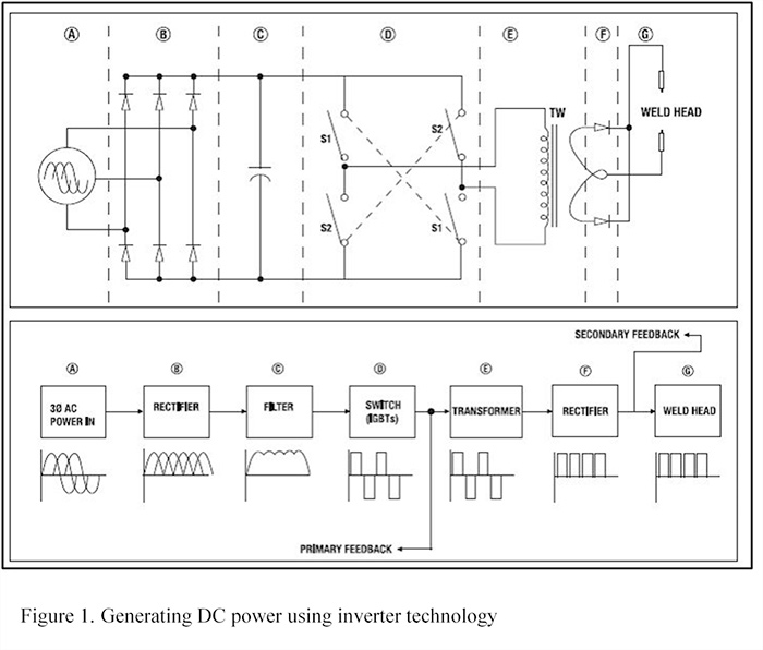
Figure 1 illustrates how the 3-phase AC power is converted to DC power, showing what happens inside the weld control system.
BLOCK A is the incoming 3-phase AC power, typically ranging from 220V to 480V in the United States.
BLOCK B is the first rectification stage, in which the incoming 3-phase AC power goes through a bridge rectifier. The bridge rectifier changes, or rectifies, the 3-phase AC power to provide a DC reference voltage. As shown in the waveform, this produces only positive pulses. The rectification process has inverted the negative half of the wave to create this DC reference voltage.
BLOCK C is the filtering stage, in which capacitors filter out the noise and minimize the ripple effect left over from the rectification process. This cleans up the waveform and results in more consistent current. The capacitors do not act as a storage medium, as in capacitive discharge (CD) style machines, even though they do store energy during this rectification. (Users should always follow manufacturers’ safety precautions, due to the amount of energy that can be stored.)
BLOCK D is the switching process, during which IGBTs use the rectified and filtered waveform and switch the output power on and off. The waveform shows that the IGBTs produce positive and negative pulses. The resulting waveform is called a bipolar square wave. The IGBTs switch on and off at a specified rate or frequency measured in hertz. For example, Amada Miyachi America controls operate at 400, 600, 800, 1000, 2000, and 4000 hertz (Hz), depending on the model.
BLOCK E is the welding transformer. The bipolar square wave is fed into the transformer, which steps down the voltage and steps up the current.
BLOCK F is the second rectifier, which is located within the transformer. In this stage, the bipolar square wave is rectified, producing only positive pulses.
BLOCK G shows the weld head.

Current feedback is configured in two ways: Primary current feedback or Secondary current feedback. With primary feedback, the current is sensed at the input to the transformer. When secondary feedback is used, the current is sensed after the transformer in what is called the “secondary loop.” In both cases the control uses the sensed current to dynamically adjust the output.
Inverter technology also allows for other feedback modes, including automatic voltage compensation (AVC), constant current, constant voltage, and constant power. One of the key advantages of the inverter welding technology is that the feedback control responds in milliseconds rather than in AC cycles, which is 16.67 milliseconds at 60 Hz. In addition, inverters can be programed in millisecond increments.
Inverter technology application examples
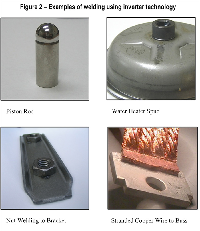
The specific advantages of resistance welding with inverter technology vary from customer to customer. However, using DC welding and inverters can provide the answer for most welding needs. Figure 2 shows a variety of examples of welding applications that successfully use the inverter technology.

 About Amada Miyachi America
Miyachi America Corporation, a leading manufacturer of welding, marking, cutting and micro machining equipment and systems, will officially change its name to Amada Miyachi America, Inc. Miyachi Corporation has been part of the Amada Group since March 2013. The name change increases the parent company’s recognition and brand awareness, while maintaining the association with Miyachi’s long and successful history as a provider of advanced technology.
The content & opinions in this article are the author’s and do not necessarily represent the views of ManufacturingTomorrow
Comments (0)
This post does not have any comments. Be the first to leave a comment below.
Featured Product

