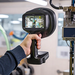
One of the first trends driving change is 3D printings transition from prototyping to commercial-grade production, combined with the increasing popularity of metal as a printing material.
3D-Printing File Formats Must Evolve with the Industry
Dave Opsahl | Tech Soft 3D
In the beginning, there was the stereolithography file, commonly called the STL file. Although not very complex—it was essentially a collection of triangles—the STL provided a way to get data into 3D-printing systems. Enough hardware manufacturers used STL for it to become something of an industry standard, providing some much-needed interoperability during the additive-manufacturing industry’s early days.
However, as the industry matured, STL’s various shortcomings came into focus. Since STL files were little more than a giant soup of triangles, they were difficult to work with. If you wanted to edit a face or reposition a part, you’d have to figure out a way to change numerous triangles—a highly inefficient and error-prone process.
.jpg)
STL files consist of a collection of triangles.
A solution of sorts appeared with 3MF, which represented the next step in the evolution of file formats. Although based on tessellated data like the STL that preceded it, 3MF allowed for compression and instancing (reduced file size). It also had the advantage of being extensible, so it supported extensions for tasks like file slicing or job management. With these extensions, the 3MF file format could evolve over time as required by the industry.
That was the idea, anyway. Despite garnering the support of a number of big companies, the 3MF file format did not see a lot of activity, due to the well-established position of STL within the workflows of the industry.
Change is Afoot
Is STL destined to stay the dominant file format for 3D printing? Not necessarily. The industry is evolving in ways that require access to the original CAD data in addition to the tessellated data that may be provided by a STL.
.jpg)
3D-printing of metal parts is becoming increasingly more common.
One of the first trends driving change is 3D printing’s transition from prototyping to commercial-grade production, combined with the increasing popularity of metal as a printing material. Heavy-duty industries like aerospace and automotive are now opting for 3D printing to create select metal parts, rather than using traditional subtractive manufacturing methods. 3D-printed parts are no longer just prototypes, but are finding their place in commercially released products. As a result, they increasingly demand access to the solid model, rather than a tessellated version of the CAD data.
Direct access to CAD data is also essential now that 3D printing is starting to incorporate traditional engineering techniques into its workflows. This includes using geometry dimensioning and tolerancing (GD&T), computational engineering analysis (CAE), and metrology for quality control.
Let’s say an automotive company printed a part and wanted to check its quality before it goes into production. During this inspection phase, they need access to the original CAD data to make sure dimensions and tolerances are up to spec. The CAD data serves as a source of “truth” for them to compare against the printed part.
A “Both/And” Approach
Today, the 3D-printing industry finds itself straddling two worlds. On one side, there are solid models and boundary representation (BREP), and on the other, tessellated or faceted models.
.jpg)
Boundary representation (BREP) and geometric dimensioning and tolerancing (GD&T) are being leveraged in 3D printing.
There’s a tremendous amount of data coming from both of these worlds. The advent of high-quality, optical scanners makes it easy to create point clouds that get turned into a mesh model. Often, this faceted data needs to be married with CAD data before it is printed. The medical and dental industries, for example, frequently combine biological scan data—such as an MRI or a CT scan of a body area—with CAD data for an implant or some other medical device.
Taking a “both/and” approach to data requires the right tools. It will be critical to find a powerful toolkit that excels at supporting advanced workflows by providing access to data from the original CAD files.
The ability to easily work with different types of data is crucial to supporting real-world 3D-printing workflows. As 3D printing continues its forward march into more industries, this capability will only increase in importance.
Through Tech Soft 3D’s partnership with Siemens comes Parasolid, a solid modeling toolkit that now supports full facet support in all modeling operations in its new Convergent Modeling feature set.
.jpg)
Continued Evolution
One of the toughest problems facing the additive-manufacturing industry has been how to get quality manufacturing data into the systems. It’s increasingly clear that while STL is part of the solution, the industry is moving in exciting new directions where access to the native CAD data is required—to be used on its own, or in conjunction with tessellated data.
File formats might seem like a relatively small aspect of the 3D-printing story, but they are how we access data. As long as the 3D-printing industry continues to evolve, we need to ensure that the proper file formats are there to support these new directions. Otherwise, we risk limiting the workflows that 3D printing is capable of handling—stopping its evolution in its tracks.
Dave Opsahl is the Vice President of Corporate Development at Tech Soft 3D. In this role, Dave explores, develops and leads company growth initiatives. Dave has a distinguished track record in business development including his role as the Managing Member of Sagemark LLC, a consulting company specializing in marketing and business development projects for manufacturing software companies.
The content & opinions in this article are the author’s and do not necessarily represent the views of ManufacturingTomorrow
Comments (0)
This post does not have any comments. Be the first to leave a comment below.
Featured Product

