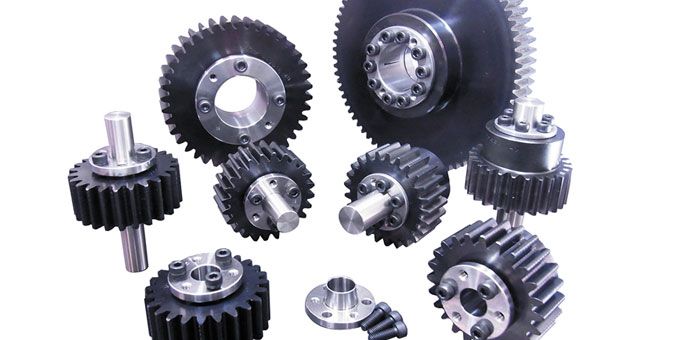
Q&A with Ronald Valenzuela, Engineering Manager, KHK Gears: As technology advances, we have seen a shift into using much finer pitch gearing. We have certainly come across more exotic gear designs in the Mechatronics field that require a much smaller design..
 Choosing Gears Best Suited for Your Application

Q&A with Ronald Valenzuela, Engineering Manager | KHK Gears
Tell us about KHK Gears and your role with the company.
We (KHK-USA Inc.) are a wholly owned subsidiary of Kohara Gear Industry (KHK) which is a world-class gear manufacturer based out of Kawaguchi, Japan. KHK is a multinational corporation with international distribution channels that spreads throughout Asia, Europe, North America, and Latin America. Under the brand trademark KHK, Kohara Gear has become the industry leader in stock gear production in Japan, commanding an 80% market share. KHK currently employs over 200 people at 2 locations in Japan. The main headquarter is in Kawaguchi and handles mainly custom products, and the production facility for stock gears is in Noda. All Kohara Gear manufacturing facilities hold both ISO 9001 and ISO 14001 certifications. We represent Kohara Gear in the North American marketplace, and, since we are not an independent distributor, we provide our customers with factory pricing for all their gearing needs.
My role here at KHK-USA Inc. is as the Engineering Manager and I oversee all engineering related activity across the North America, Canada, and Mexico territories. My team and I are tasked daily with offering custom engineered solutions for various applications, as well as, providing design and technical assistance of our entire product line to all our customers. Our core business lies within the power transmission, packaging, and industrial automation industries. We thoroughly analyze a customer’s application and requirements in order to design a proper gearing solution. Even if a customer already has a design in mind, it is our job to review and propose a tailored solution to their request, based upon the given information and always keeping in mind production feasibility, scalability, and more importantly cost.
What is module and how does it differ from diametral pitch?
The most popular designator for pitch outside of the U.S. is what is known as module. To determine the value of module for a given gear, you measure the pitch length in millimeters and divide that value by π. For example, if the pitch length measured 9.425mm, this would be a module 3 gear. By incorporating π into the value of pitch, the metric dimensions of a spur gear are very simple to calculate. The pitch diameter of a module 3 spur gear with 25 teeth is equal to the module (3) multiplied by the number of teeth (25), or 75mm. It also simplifies the calculation for addendum, dedendum and whole depth. For a DP gear, the addendum is equal to 1/DP, the dedendum is equal to the whole depth minus the addendum, and the whole depth is equal to 2.157/DP. When dealing with module, the addendum is equal to the module, the dedendum is equal to 1.25 times the module, and the whole depth is equal to 2.25 times the module.
Similar to DP gearing, standardized module values have been established. For course pitch power transmission gearing, the typical values for Module are 10, 8, 6, 5, 4 and 3. For medium pitch fractional horsepower gearing, the values for module are 2.5, 2, 1.5 and 1.25. For fine pitch instrument drive gearing, the typical values are 1, 0.8, 0.7, 0.5, 0.4, 0.3 and 0.2. Within metric gearing the concept of circular pitch (CP) also exists. By subtracting the value of π, CP values of 2.5mm, 5mm, 10mm 15mm and 20mm are common.
Can you give us some tips on how to choose best gear type for various applications?
This is a common question that my team and I come across each day. The real answer is that every gear type offers unique advantages based on the gear geometry and mesh characteristics.
In order to find the proper style of gear for an application, the first consideration needs to be what gear type will fit with the shaft orientation of the system. The possibilities are:
- Parallel Axes
- Intersecting Axes
- Nonparallel and Nonintersecting Axes
Since every solution will always be application specific, the following information must then be established:
- RPM / Gear Ratio
- Load / Torque / Duty Cycle Requirements
- Environment in which it will operate
- Housing Restrictions
- Target Pricing
Once we have a full understanding of what is required, we can offer a suitable solution that is based on the specific parameters of the application. It is important to note that spur/helical gears are the most commonly used because of the wide range of tooth configuration available and their flexibility to be applied to many mechanisms. For example, two spur gears can mesh in a parallel shaft mechanism allowing for motion to be transmitted and direction to be reversed, or a pinion can mate with a rack thereby converting rotary motion into linear travel, and finally a spur gear can be part of a planetary gear mechanism in which it will mate with an internal gear and be used as a speed increaser or reducer.
How does gear quality affect the overall performance of the mechanism?
Precision is key when it comes to delivering an efficient gear solution. A high-quality made gear will reduce noise level, backlash, vibration, and allow for a smaller design envelope. All these benefits greatly increase the efficiency of the mechanism and will guarantee a well-engineered product once it is assembled.
We receive many inquiries from numerous clients that have previously sourced low-quality gears from different vendors and express their frustration when their QC department must refuse the product because the gears failed to pass inspection, or the gears failed during the prototype phase. We pride ourselves in offering high-quality gearing and we have the necessary processes set in place during production to minimize defects.
With all the new type of fiber-infused-plastics in the market is steel still the best option? When might a fiber-infused-plastic be the best option?
There are many new plastics that are flooding the industry, however, they do come with a high price tag. It really depends on the type of project, scale, and funding available for each application. Steel will always be the best option for applications that require high-strength, precision quality, and affordability. Also, because of its machinability properties, the production cost for some steel components can be significantly lower when compared with certain plastic materials.
Fiber induced plastics are ideal for applications that have weight restrictions but require a decent amount of torque to be transmitted. These materials can be exposed to corrosive environments or have harsh chemicals introduced during operation and have no negative side effects. Their ability to absorb shock or vibration along with their low coefficient of friction make them highly recommended for applications that require the gearset to be self-lubricating or where noise levels are a cause for concern. Certain materials such as PEEK, provide a high strength-to-weight ratio advantage that we have noticed a large increase in usage over the past decade.
Plastic gears can also be introduced as a fail-safe in a complex drivetrain. When used as a fail-safe, the designer acknowledges that the system could suffer a catastrophic failure, and by including a sacrificial nylon gear in the system, they can prevent damage to the rest of the drive. When the system experiences a peak load exceeding that of the design, the first component to fail will be the plastic gear.
What are the benefits between a straight tooth and spiral tooth design?
Straight tooth design offers the most simplistic type of gearing available, making it ideal for applications that require a gear mechanism at the most affordable price. The most favorable benefit for choosing straight tooth design would have to be the wide variety of pitch and tooth configurations that are readily available in the market place. Furthermore, straight cut gears offer much shorter production lead times and lower production costs.
Listed below are a few of the drawbacks that are associated when selecting a straight tooth design:
- Limited torque capacity
- Higher noise levels during operation
- Lower contact surface area
A spiral tooth design incorporates a helix angle that amplifies many of the core strengths of a straight tooth design. The helix angle extends the contact surface area of a gear which allows for higher torque capacity to be transmitted. In general, spiral tooth gears offer a much stronger, quieter, and smoother gear mesh.
Listed below are a few of the drawbacks that are associated when selecting a spiral tooth design:
- Creates or intensifies axial thrust forces
- Left-Hand and Right-Hand versions are needed
- Higher production cost
- Longer Lead times
With manufacturing rapidly changing what changes have you seen in the types of gears in demand?
As technology advances, we have seen a shift into using much finer pitch gearing. We have certainly come across more exotic gear designs in the Mechatronics field that require a much smaller design envelope than ever before. Designs are becoming much more space and weight conscious, and the mechanism have much tighter restrictions than what we were used to seeing. Lastly, there has been a noticeable spike in the use of all the new different types of fiber-infused plastic materials that are becoming available.
How does KHK Gears adapt and stay relevant with the ever-changing customer demands now?
We are able to adapt because we constantly invest in our work force and properly train them in gear design, fabrication, and quality control. A well-rounded employee will always give the company a competitive advantage over its competition and offer a pleasant experience to the consumer.
We listen and pay attention to our customers and the industry trending topics. Our customers are the primary source when trying to recognize industry trends and opportunities, they can shine the light on many issues that we may have overlooked. We also attend many trade shows and conventions throughout the year, the interpersonal exposure we get with both industry leaders and potential clients give us a direct outlook on trending topics or advancements within the industries that we operate in.
The content & opinions in this article are the author’s and do not necessarily represent the views of ManufacturingTomorrow
Comments (0)
This post does not have any comments. Be the first to leave a comment below.
Featured Product

