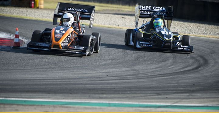
The Formula SAE is a student design competition organized by SAE International. The goal is to design and manufacture a Formula-style race car under very strict regulations.
 Rapid Prototyping Helps University Students Design Racing Car

Case Study from | Smart International
The Formula SAE is a student design competition organized by SAE International (previously known as the Society of Automotive Engineers, SAE). The goal is to design and manufacture a Formula-style race car under very strict regulations, where the ingenuity counts as an advantage within very narrow margins. The prototype race car is evaluated for its potential as a production vehicle. Each student team designs, builds, and tests a prototype based on a series of rules, whose purpose is both ensuring on-track safety (the cars are driven by the students themselves) and promoting clever problem-solving.
Formula SAE encompasses all aspects of a business including research, design, manufacturing, testing, developing, marketing, management, and fundraising. Each team is made up entirely of active college students (including drivers).
Composite materials, elaborate and expensive machining projects, and rapid prototyping are used as innovative weight-saving strategies. Furthermore, 3D printing offers the possibility to iterate parts continuously with reduced costs. The cars are tested and qualified according to their safety, design, maneuverability, performance, and acceleration. Particularly, the jury looks for improvements with regard to tests of previous components to be able to see the advances and the ingenuity of the equipment.
The ITBA (Technological Institute of Buenos Aires) located in Buenos Aires, Argentina is a renowned university throughout Latin America and the world. The ITBA team led by Prof. Juan Zubiri (first on the right) has been competing in the SAE FORMULA for some years and in 2018 has achieved second place in the Brazil competition.
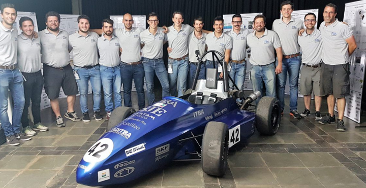
The team of mechanical, electrical, and electronics college students works informally on the project, receiving support from various sponsors. Students build and test the SAE vehicles directly at ITBA premises, equipped with water cutters, CNC, lathes, 3D printers, as well as fatigue test machinery (for suspensions, general fatigue, etc.).
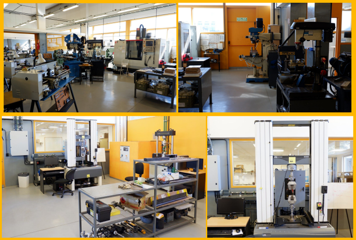
ITBA manufacturing lab and testing facilities.
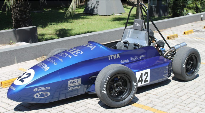
3D printing accelerates R&D, improves design lead time, prototyping workflow and precision required to manufacture parts in a variety of engineering materials.
THE PROBLEM
At the time ITBA introduced the KODAK Portrait 3D Printer, the team was facing a redesign of the components of the wheel hub and the spindle, as formula SAE fosters the development and improvement of the parts instead of their replacement.
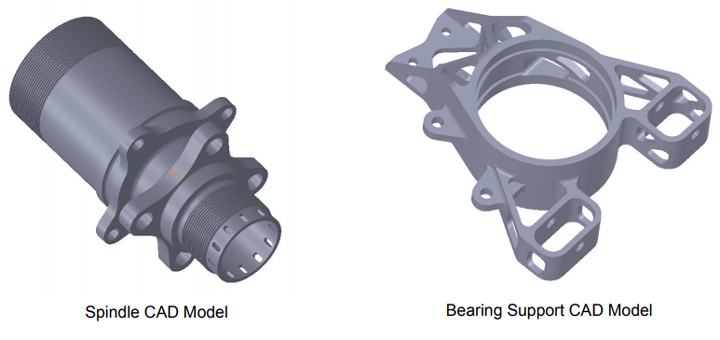
The first challenge was to optimize and reduce the weight of all components of the wheel hub and the spindle, taking into account how all of these components interact with the wheel, suspension, brakes, hydraulic brake wiring, and steering. For this reason, it was imperative to confirm that all these parts were able to operate together correctly by means of 3D printed prototypes. The team was working on new improvements which needed to be validated before moving to machining the final part.
Editors Recommendation "Rebuilding Components With Reverse Engineering"
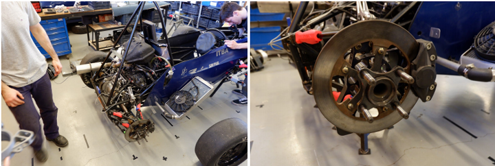
The team began with the components of the wheel hub and bearing support to make the first dimensional studies of the part, it was proceeded by placing them in the chassis of the car to see how they would fit and their relationship with other components. The redesign achieved a reduction of weight through the implementation of various subtractions creating a more detailed morphology. Within a few days, the 3D printed parts were produced and mounted on the car and were validated after only 2 iterations.
THE PROCESS
To be able to withstand the slight friction generated by the interaction of the moving components, the parts were printed in ABS. It should be taken into account, that in this case the friction was not the result of the actual use of the vehicle, but of the manual movement performed in the test bench to verify that everything behaved within the expected ranges. As ABS is a material that tends to shrink slightly after being printed, such a percentage deviation was calculated and the part scaled.
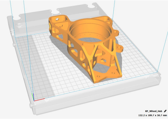
STL file in the KODAK 3D Slicer
Models were prepared using the KODAK 3D Slicer with the preset material profiles. Thus students only needed to position the model on the print bed and select the desired material profile, this process simplified the learning curve by avoiding the need for extensive knowledge of 3D printing settings.
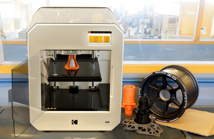
KODAK ABS Filament is a high-grade quality ABS, engineered to be easy to print with reduced warping, shrinkage and no delamination.
- High mechanical resistance to all kinds of stress, especially impact.
- Diminished warping allows for printing faster without the risk of model detachment.
- Diminished delamination allows for construction of highly resistant parts.
- It can be post-processed using acetone to grant a shiny smooth surface.
 THE RESULTS
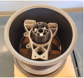
1:1 Scale model of the wheel hub and spindle to check model, dimensions, and interaction with the rest of the parts.
3D printed components positioned along with the magnesium alloy rim and components of the transmission. The magnesium rim is an extremely delicate component, the printed parts allow for rapid positioning and verification of design aspects without the need to risk hitting or scratching the part with metal components.
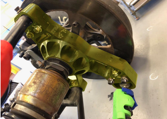
Previous wheel hub (highlighted in yellow) before improvements: it can be noticed the steel structure is bulkier and heavier.

These parts were mounted on the vehicle along with all components such as the wheel, brakes, suspension, and chassis. It was verified that the movement was adequate in all axes of work of the vehicle and the parts did not clash with each other. This allowed the validation of the model which could finally be sent for production by CNC machining.
LOOKING FORWARD
3D printing is triggering a change in the way more and more disciplines, related to the industrial field, can make progress in shorter times than in the past. With this new tool, today’s engineering students are empowered to change the way they build and design their projects; with even easier solutions at their fingertips, that simplify teamwork, project sharing, and printing with cloud monitoring. There are many types of engineering degrees that take direct advantage of 3D printing. Just to name a few:
- Mechanical Engineering
- Materials & Chemical Science
- Electronic Engineering/Mechatronics
- Civil Engineering
- 3D Modelling/Industrial Design
For instance, as shown in this case study, the automotive industry, as well as aerospace, benefits from much shorter lead times than associated traditional engineering methods, such as casting or machining, allowing for much faster development and testing of components.
The development of a competitive racing car in just a few months is a highly delicate and complex process. 3D printing has made accessible a tool capable of manufacturing all kinds of highly complex parts at a greatly reduced cost compared to other tools. Unlike other manufacturing techniques, where the complexity of the piece increases the cost exponentially, with 3D printing the complexity of the part is irrelevant to cost. This is a key factor in this type of undertakings since it allows engineering teams to create and iterate parts successively without worrying about complexity, lead time and cost.
3D printing greatly reduces project expenditure, one 3D printer can be a substitute for several other tools, and widen the possibilities to use a broad variety of advanced materials such as ABS, Nylons or TPU.
If you like this article you may like "Advanced Metrology Tools Enable Reliable Engine Light-Weighting"
The content & opinions in this article are the author’s and do not necessarily represent the views of ManufacturingTomorrow
Comments (0)
This post does not have any comments. Be the first to leave a comment below.
Featured Product
